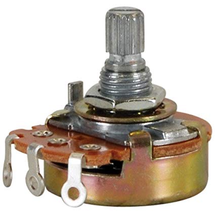
As part of my PhD research, we used an onboard motor to control the speed of flowing water so that we can measure the fish’s response under different conditions. Prior to joining the lab, the PI had a device called a potentiometer which intercepted the voltage to the motor. By adjusting the knob of the potentiometer, more or less voltage would pass through and the motor would either turn faster or slower.
Data collection consisted of turn the knob, collect data for an hour, turn the knob again, collect more data, and so on. I decided this would be a good place for automation. Because we had 5 different voltages we wanted to set it to, I set out to design a set of chips that each contained a resistor corresponding to that particular voltage.
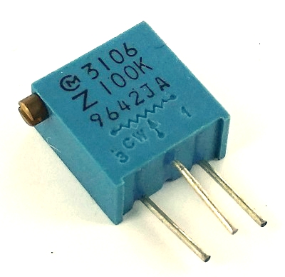
I measured the resistances across the potentiometer for the five speeds we were using, and designed five boards to match these settings. Each board contained a PNP transistor, a double-gated switch, diodes, two fixed resistors, and two trimming potentiometers (variable resistors.) There was a small amount of voltage going to the transistor. When tripped, the transistor would allow the larger voltage to flow between the power supply and the motor, adjusted by the chip’s particular resistance.
The voltage to the transistor itself was controlled by the computer, via the parallel port. I was able to write some C++ scripts that use the io library to control the port and turn a particular chip on a time.
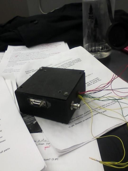
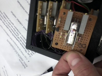
I placed the chips inside of a box and affixed a parallel port male connector.
A few months later, I built a device identical to this first one in order to incorporate more speeds. However, there was a small problem. I now have 10 units, while the parallel port only has 8 pins that can be programmatically controlled. Thus, I was forced to build a ‘master’ chip which would delegate control. Using a similar set-up (computer control of transistor base) with many more switches, I was able to send a byte and set the motor to one of ten different speeds.
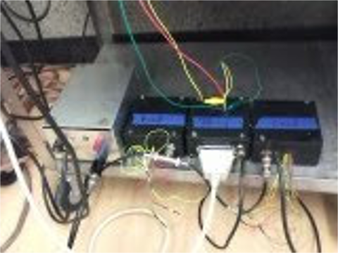
I’m relatively pleased with the appearance of the final product: it has a parallel port interface attached to the case, all transistor connections are hidden from view, and each of the two sub-units can be used functionally on their own (by only changing the byte sent from the computer.)
Again, all the code for this project (including the parallel port executables I wrote) is available on GitHub.